Lighting Making some LEDs

Would u know if that particular driver is of the Constant Current or Constant Voltage type? I'm pretty sure with the Mean Well HLG series, the ones that end in 24, 36, 48 are constant voltage, and the ones ending in 700, 1050, 1400,/1750, 2100 etc are constant current. I use Constant Current drivers as noted by their C status. Like HLG-240h-C1050x. The C before the 1050 means its Constant Current @ 1050ma. Anyway, I have ALWAYS wired the C series Mean Well in series wiring, and the other series in parallel. For example, I am building a COB as we speak with my buddy. We are using the HLG-185-36a driver in parallel with 4 Citizen 1212s. So the instructions you gave me are for parallel wiring for your ebay driver. So I am gonna assume its not a CC driver, but a constant Voltage driver. Basically, treat every one of the 10 strips as its very own "unit." Each unit has a + and a - terminal (Red + /Black - ). Basically make sure that every + on the whole kit is hooked together to the red + output of the driver and all of the - is hooked together and gets to the black - side of driver output. I'm sure your kit plays nice together of you don't fuck up. Make sure to keep your wiring neat. No stray wires or bare copper. Use wire nuts

Sent from my XT1254 using Tapatalk
 
@Dr.Bubbles I'm not sure what any of that means about the driver.. I'll message them and see what they say.
Are there any videos/pictures that would show what I'm doing? I feel super slow for not understanding this, hahaha.
 
It sounds like you got a complete kit. If they selected the driver for you, and gave u parallel wiring instructions, have at it and let me know how of went. Of its "true diy" then you have to figure this out yourself. There is no definitive right answer here.....Its all preference and what works. Like I said....Assuming the driver is correct for your project, just wire it according to the instructions, which seem to be pointing to a parallel wiring job. There is two ways to do this. [HASHTAG]#1[/HASHTAG] is imagine a aluminum straight ladder. Just like your strip lights. The rungs represent the LED diodes. One side of the ladder (right for example) is +, the other side (left) is -, also known as negative. The rungs are your devices being wired in parallel. Each one spans the gap from positive to negative. If you break a rung, power still flows through the ladder rails on to the next one. So, of one diode fails, the rest are still lit. That's parallel wiring in the "daisy chain" method. You can also just connect all the positives together and all the negatives together off a single lead wire each. Its the same in the end electrically speaking. Series wiring is different, but pretty simple, as its what kids are doing in 4th grade hooking a light to a alkaline battery around in a circle. Parallel looks like a ladder and series looks like a complete circle. Also, with series you will have positives into negatives oe vice versa, and with parallel only positives will be hooked to other positives. Send some time looking at some electric simple circuit for beginners. You gotta know at least a little bit if electrical work to do the DIY stuff, even following instructions. Spend one hour and you will learn much. Good luck.

Sent from my XT1254 using Tapatalk
 
The person who recommended the driver said it's a CV.
Is this what I'm doing?
par_lrg.gif
 
Last edited:
@Dr.Bubbles
Could I just use a bunch of these things?
 

Attachments

  • diagram.png
    diagram.png
    10.1 KB · Views: 76
  • connectors.png
    connectors.png
    304.4 KB · Views: 83
Last edited:
Okay so.. they sent me a picture of their's and I have no idea what's going on, hahaha. So I kind of played with the wires some.. Lmao
To do the ladder thing... Do I have to have the positive going into a terminal on one end and then use the negative terminal on the other end? Or can I just use the terminals on one side like in the first diagram? (2 posts ago)
0726171743a-jpg.2334824
 

Attachments

  • 20596983_256931211477667_2467347922480844237_n.jpg
    20596983_256931211477667_2467347922480844237_n.jpg
    100.5 KB · Views: 102
  • 20622054_256931228144332_6723237146650166249_n.jpg
    20622054_256931228144332_6723237146650166249_n.jpg
    99 KB · Views: 108
  • 20621819_256931248144330_4176074134060287220_n.jpg
    20621819_256931248144330_4176074134060287220_n.jpg
    60.4 KB · Views: 81
  • 0726171743a.jpg
    0726171743a.jpg
    97.5 KB · Views: 75
Last edited:
That bottom picture is difficult to understand. Its DEFINITELY a parallel wiring job though. The 1st diagram u provided was a perfect guide to follow. And those little crimp on grabbers will work....I would use a better connection personally. Same idea, just a better connection. You need a food connection to get all the current through. Voltage is pretty hit or miss, but current, which is measured in A for amps or ma for milliamps, which is 1/1000 of an amp. So 1050ma is 1.050 amps. And volts x amps = watts.). Anyway, to get all the current through, use solid connections, and solder or use Wago connectors or equivalent. And the first diagram is solid. As far as the ladder approach, look at the left and right main rails as your two wires. They NEVER touch. The rungs bridge the gap, and they represent the component being powered up. That's parallel wiring, hence the parallel appearance of the ladder/wire, and also of the components up the rails/wire. C.V. drivers usually get wired in parallel, so just give it a go. Remember...No red should EVER touch any black, and vice versa with parallel.

Sent from my XT1254 using Tapatalk
 
@Dr.Bubbles
Alright I think I'll give it another go today. I was looking at Wagos and wire nuts, I just figured these looked neater, since the others would have to stick out all weird. But I suppose if they don't work that great, I'd rather just go with the other stuff.
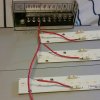
So.. I am confused again a little though? They told me that what they're doing is this, and that it's what i'm supposed to do, and said this is parallel and it's the same thing that they did with their's but.. isn't this series?
quote; "Mine only have one set of terminals at one end, so I have to have two wires in each terminal. Yours have terminals at each end. Think of it like putting strings of Christmas lights together. The end of one just plugs into the end of the next one."

strips-jpg.2335322
 
Last edited:
@Dr.Bubbles Okay... I wired them according to the diagram he sent. It's okay like that right? I thought that was what I was sipped to do initially but I messed up cause I got confused about the series type.. and now I think I get the idea that series is when you connect positives and negatives together and parallele is just.. running them without ever touching. I feel dumb AF right now, lmfao. Like.. my god, I've been beating dead horse all week. I only have ONE more question. Should I set my power supply to 115v or 230v o.o
 
Last edited:
@Dr.Bubbles @namvet25
Done! Well kind of. They're on a temporary framing for now, I don't like the flat bars I ordered, they're more bendy than the strips. And I gotta get my lower fan situated better. They're oscillating and I can't use the giant clip anywhere down there so I have to make up for that.
I literally just beat a dead horse for a week. The wiring I just did is exactly what I tried to do before, but I guess I got confused because someone had told me I need to have the positive going in the first strip, run all the wires, and would have a black hanging out that i'd put into the terminal, and that's really not how things went, and then all the things that said series looked the same so.. Yep. :doh: I apologize for my.. Lack of brain usage. But hey.. I learned some shit!

Thanks for all the help man! Now I can start my girls, and start getting into the stuff I actually understand! :woohoo:

20706011_257405671430221_1369966309_o - Copy.jpg
 
Back
Top