DIY DIY - Affordable? Soil NPK, pH & EC sensor (NPKPHC-S)

Hey Friends :cheers:


For those of you, I haven't reached...Happy New Year!!! :yay:

The tinkerer in me didn't lay low during the holidays...I've mounted the NodeMCU which controls the Extraction fan. Just disconnected the 'original' potmeter and replaced it with the digital potmeter. Easy peacy... :toke:
Digital Fan Control Schema.png


If there is anyone interested in the code...
C++:
#define BLYNK_TEMPLATE_ID "TMPLxxxxxx"
#define BLYNK_DEVICE_NAME "Device"
#define BLYNK_AUTH_TOKEN "Token Here"


// Comment this out to disable prints and save space
#define BLYNK_PRINT Serial


#include <ESP8266WiFi.h>
#include <BlynkSimpleEsp8266.h>
#include <FastX9CXXX.h>

//Potmeter pins
#define X9_1_CS_PIN 4
#define X9_1_UD_PIN 2
#define X9_1_INC_PIN 0


char auth[] = BLYNK_AUTH_TOKEN;

// Your WiFi credentials.
// Set password to "" for open networks. --> never do this IRL
char ssid[] = "SSID Wifi here";
char pass[] = "Password Wifi here";

FastX9C103 Potentiometer1(X9_1_CS_PIN, X9_1_UD_PIN, X9_1_INC_PIN);

int step1 = 0;


BLYNK_WRITE(V2) {
  if (param.asInt()) {
    step1 = param.asInt();  // assigning incoming value from pin V2 to a variable
    Potentiometer1.JumpToStep(step1, true);
    Serial.print("step1 value:");
    Serial.println(step1);
    Serial.print(F("Potentiometer 1 current resistance: "));
    Serial.print(Potentiometer1.GetEstimatedResistance(), DEC);
    Serial.println(F(" Ohm\t"));
  } else {
  }
}

void setup() {
  // Debug console
  Serial.begin(115200);

  Blynk.begin(auth, ssid, pass, "192.168.0.100", 8080);  //Use a local Blynk server on a rPi as Blynk IOT is not free anymore!!
}

void loop() {
  Blynk.run();
}


Next up I've been working on integrating the heating mat in the system. I've put together a NodeMCU with a Solid State Relay because we are going to switch a resistive load. Didn't think about the placement before gluing the NodeMCU to the casing. Had to cut a piece from the connector to make it fit the USB socket... Stupid :wall:
1672770481879 _small.jpg


Instead of cutting the wire from the heating mat, I decided on harvesting the outer parts of an extension cable. Surprisingly this costs as much as a male and female plug bought separately, go figure... Should have ordered a couple of buck converters then I could have swiped the power from the 220V AC and I could have parted with the extra usb cable for 5V. Maybe a upgrade project for the future...
1672770481883 _small.jpg


This device receives temperature data from another NodeMCU, which has the DHT44 sensor attached and uses that to switch the relay on or off.
In the Blynk App on my phone I can set the desired temperature.
Anyway...the code for this project...
C++:
#include <ESP8266WiFi.h>
#include <BlynkSimpleEsp8266.h>

char auth[] = "Token here";
char ssid[] = "SSID Wifi here";
char pass[] = "Password Wifi here";

int relay = 4;              //relay switch
int i;
float tempData;               //input room temperature
float setPoint;               //input wanted room temperature from Blynk App


// Timer for blynking
BlynkTimer timer;

void setup() {

  Serial.begin(115200);
  Blynk.begin(auth, ssid, pass, "192.168.1.155", 8080); //Use a local Blynk server on a rPi as Blynk IOT is not free anymore!!
  Blynk.syncAll();
  pinMode(relay,  OUTPUT);
  timer.setInterval(5000L, runMe);

}

void loop() {
    Blynk.run();
    timer.run();
}

BLYNK_WRITE(V0){
  i = param.asInt();
  digitalWrite(relay, i);
}

BLYNK_WRITE(V4){
    setPoint = param.asFloat();
}

BLYNK_WRITE(V5){
    tempData = param.asFloat();
}


void runMe() {
  Serial.print("Temp: ");
  Serial.println(tempData);
  Serial.print("Setpoint: ");
  Serial.println(setPoint);
  Serial.print("Relay: ");
  Serial.println(i);

  if (tempData <= setPoint - 0.2) {
    digitalWrite(relay, LOW);
    Blynk.virtualWrite(V0, LOW);
  }
  else if (tempData >= setPoint + 0.2) {
    digitalWrite(relay, HIGH);
    Blynk.virtualWrite(V0, HIGH);
  }
}


Regards,

Bob :toke:
 
Hey Friends, Growers & Blowers :toke:


It's been quite a while since I've updated this thread of mine. Mostly because I've been busy doing other stuff, but also because everything is going so well with the BioTabs nutrient line. Their was no immediate need to know the NPK, PH, EC values for the soil as my bennies are regulating everything without my interference. :thumbsup:

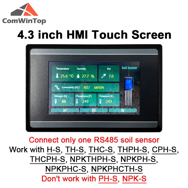
Now, recently I was window-shopping on Aliexpress and came upon this touch screen specifically made for the sensor I had bought.
Measure-Soil-Moisture-Temperature-Humidity-EC-PH-NPK-4-20mA-0-5V-RS485-Modbus-Soil-Sensor.jpg_640x640.jpg


Cool right? Well, I pondered over the following question. Could I make this from separately sourced materials? Yes, but not for the price this seller is selling it. As I normally do, I check the rest of Ali to see if there's a cheaper seller, but for one reason or another, this is the only seller on Ali that sells the screen to go with the sensor. Also, and I figured this out later on, this is the official seller for ComWinTop, which is the manufacturer for all kind of neat sensors, check his store out for ahum...a PAR sensor :hump:

Anyway, as these sellers on Ali usually contact you to make sure you're order is right and to thank you for your order, I got to talk with him over the chat channel on the app and told him I'm a member of this neat forum and that I always record my hobby related doings in all sorts of threads. That I already had bought the NPKPHC-S sensor in the past to couple it to a ESP32 device, but that I just didn't have the time to build and code everything and that the sensor had been lying in a drawer somewhere until I found his page while window-shopping. Now I could finish my NPK sensor thread on AFN! :jump:

So said so it be done...Eight days later a box was waiting for me when I got home from work...And besides the screen the seller added the better NPKPHCTH-S sensor along with it ♥
That's just amazing!! Thank you dude :thumbsup::pass:
1691594317078 _small.jpg


I contacted him via the chat and his reply was..."Better to show the device with the NPKPHCTH-S sensor. Have fun with it ;)". Amazing, right?!!
So, here is this guys store --> https://www.aliexpress.com/store/910369336?spm=a2g0o.detail.0.0.40ccYeSPYeSPpM
and here is the link to all the sensor combinations and touchscreen --> https://www.aliexpress.com/item/1005001524845572.html

Ok, let's continue. So yup the NPKPHCTH-S sensor. Measures NPK, PH, Conductivity, Temperature & Humidity all in one package. The communication runs over RS-485 Modbus, which if you know the commands to send, you can even run from a serial interface, which makes my makersbrain tingle :yay:
Voltage wise this is an amazing product as you can run it from 9-30V DC, so about any leftover power-supply can run this device! WinWin!!

1691594317074 _small.jpg


This is the device with everything plugged in. I used a sickly looking Chinese money plant to actively monitor using the sensor, while making this thread.
1691594317058 _small.jpg


After warming up for a while the values stabilized and we can almost directly see what's wrong with this little plant...The pH is out of whack and the soil is deprived of nutrients. But that's not why where here for...This is the frontpanel of the screen.
1691594317054 _small.jpg


One can directly see that this device is purposly build to be placed in some sort of panel. Most likely a collection of these devices monitoring several different sensors. Which I'll come back to in another post :eyebrows:
Anyway, I can see myself fitting this in a larger case, adding some sort of battery-pack and using it in the field, where there's no electricity at all...Food for thought... 🤔
1691594317026 _small.jpg


The backside of the device. Yup, you can insert a micro-sd and log all your data to the card...Nice!!
Right next to it there's the connector for the sensor and power supply. This can be unplugged to screw everthing thight so you don't damage the board inside. :thumbsup:for that one you guys!
Then...two things that tickled my makers brain... The USB slot and RX/TX slot, which where both closed up. Usually this means there's probably a design out there that utilizes one or both alongside the RS-485 connection and SD slot. But more on that in a later post 👌 Yes, we're going into the bowels of this beast my friends 🤟
1691594317045 _small.jpg


When we boot up the device there's a nice bootup image for a couple of seconds...
1691594316976 _small.jpg


...before it lands on this default view, showing all measured values.
There's only one remark I can give here and that is, there's no measuring unit for the NPK value's. But a quick look in one of the following pictures showes that it's measured in µS/cm². Maybe they can fix this in an upcoming firmware? which is at v1.1, which we'll see later on.
1691594317054 _small.jpg


When you press the lower left corner button you go to the graph area. Which is one of my favorites as I just love graphs ♥
1691681660616.png


The first graph you'll see is the Temp/Humidity one. A handy oversight of both temperature and humidity. I would have loved to see a dual Y-axis implemented in this screen. But I can see why they used only one as the temperature range goes from -40°C to 100°C. Luckily humidity has a similar range going from 0 - 100%.
Anyway, the screen refreshes and scrolls to the right. Showing the newest value on the left side. 👍
There's only one commercial flaw in this and that there's no way to change the °C to °F. Luckily that's only one mathematical calculation ((0°C × 9/5) + 32 = 32°F) away easily fixed in a updated firmware.
1691594316959 _small.jpg


When pressed on the PH button you'll enter this view. Sorry for the picture (and the next ones), but I should have let it run longer, then the line would be much more visible. 🤫
1691594316955 _small.jpg


Next we have the EC or Electrical Conductivity. Value's in µS/cm². I can forgive the use of u instead of µ and not using the ² because many of them screen driver boards don't support "special" characters. Been there in the past...
A cool fact for those that use TDS or Salinity. The sensor can be asked for those values as well via a serial command (later on that subject ;) )
1691594316951 _small.jpg


And lastly, the NPK screen. Again the nice overview with the values ánd units 👌
1691594316945 _small.jpg


Pressing the 'Back' button
1691684170628.png


you enter the first screen again
1691594317054 _small.jpg
 

Attachments

  • 1691681713237.png
    1691681713237.png
    211.1 KB · Views: 11
Last edited:
And pressing the lower middle button...
1691684342196.png


Will get you into the Data Log screen. Here you can see the last 1900 the device holds in it's memory or write it directly to the SD card. Haven't tried this last one yet as I really don't have a direct use for the logs as I want to use it to see how my soil mixture turns out after adding all the amendments. Might do a longer measurement, where the SD card will come into play, but that's for way later :smokeit:
1691594316941 _small.jpg


Pressing that 'Back' button again will return you to the main screen and pressing the lower right button...
1691684651887.png


...you enter the Setting screen.
The first submenu (left side) is 'System', which allows you to enter a couple of values, which the first two shouldn't be changed. The system time is preferably changed to your local time, which I did for my device.
1691594316935 _small.jpg


Pressing the calibration button will take you to the...well you've might have guessed... To the calibration screen. I'm going to make a separate post about this one at a later date, but I need to collect my standards first.
The calculation for most values is based on the linear equation in slope-intercept form. How it works I'll explain in that said post 🤞
1691594316930 _small.jpg


Pressing the reset button show the following screen. I which you can reset the NPK sensors. I'm guessing this is a way to reprogram the electronics inside the sensor that do the calculations. Look at it as firmware for the sensor. And coming right out of the box should be done once. I did it via the pc application that came with the order, which allows you to reprogram all three with one command. (More about this in another post)
1691594316924 _small.jpg


And with this we come to the end of my presentation of this cool looking sensor/touchscreen combo. :coffee:
What do I think of this machine? Well I like it a lot. The English is good and besides a couple of cosmetic issues I'm carefree in working with this device. What could be a dealbreaker for our Stateside and UK friends is the fact that the temperature isn't selectable between °C & °F. ie, In the Settings screen. Cause we all know how much these guys love their imperial measurements :shrug:while we all know that metric rules :haha: Sorry, had to say it guys :cheers:
How well the sensor works I can't really say with any certainty as I need to do some measurements first. And to do that I need to have standards for every measuring unit. Luckily I have a mate whose a lab guy and he told me I already have the raw ingredients for the NPK, the standards for pH and EC are dirt cheap and temperature can be calibrated with a standard alcohol or mercury thermometer, which he will lend me under supervision, lol. This means he's standing right beside me and probably be the one holding it, but that's ok. I love 'm :pighug:


Anyway,

I hope you guys have enjoyed this epistle of a post and please join in or ask questions if you have any :thumbsup:


Regards,

Bob :toke:
 
Last edited:
So...That USB and TX/RX tags surely triggered my interest. Being a maker and seeing screws, my only thought was, where's my Phillips screwdriver?
1691594317049 _small.jpg


Upon opening this device, one notices that there's three pcb's, the one on the left is used for all the inputs and outputs. The board with the black sticker is the main board with a nameless 88 pin mcu, probably the MAX32680. If that's the case, the mcu has bluetooth on board and this could be a feature in an upcoming firmware update? and the one on the right is the screen and touchscreen controller.

Anywho, the USB and TX/RX... The top black circle is where the TX/RX pins are, but one can see that there are some parts missing, a couple of diodes and capacitors. Populating these would most likely give one access to the serial interface of the mcu. But this isn't a electronics forum, we're just inside to see what's possible...
Then the USB. This also is missing a couple of parts which are marked inside the black circle. Populating these will directly connect it through to the mcu, which makes me think, both have been omitted to prevent copying the product.
I guess the only way to upgrade the firmware will be to use the SD slot, which is something many vendors use.
1691594317021 _small.jpg


So inside there's not much we can see that would allow for a hack? Or maybe there is...I found out that one of the chips on the leftside board is a fully compliant RS-485 module, meaning you can connect up to 255 slave devices on this thing :eyebrows:
Even though in the manual it states not to connect multiple sensors to the screen it is possible, BUT ONLY after giving the second sensor a new slave id.
You do this by connecting the sensor via a RS-485 to USB convertor to a Windows computer. Running the accompanied software that came with the sensor and changing the 'slave address' to for example 2.
1691594316968 _small.jpg


Before connecting anything, please unplug the adapter from the wall!!
Then just add the wires from the second probe according to color to the block
1691594317037 _small.jpg


And after checking your connection is tight, you can plug in both the screw block into the screen and the power supply into the wall socket
1691594316916 _small.jpg


Next go to the 'Settings' screen and change the ID of the connected sensor from 1 to 2. Press 'Back' and you'll have the values for the second probe. 👌
I can see this working in the field as well. RS-485 has a maximum distance of over a kilometer! So if you put one monitor in the middle of the field you can get some distance between them sensors...Very interesting indeed!!!
1691594316935 _small.jpg


This shows the value's from the second sensor I connected. Showing the fact that I don't have value's for Temperature and Humidity. To which I only have myself to blame as I cheaped out at the time of purchase, thinking temperature and humidity aren't as important...
1691594316911 _small.jpg


So do as I say and not as I do. Get the NPKPHCTH-S alongside your flashy screen and you won't be disappointed
1691594317066 _small.jpg


Regards,

Bob :toke:
 
Last edited:
Incredbile stuff, Bob! I am beyond impressed. Although, most of the code stuff is ancient Egyptian to me.
Then you're in luck, as with the touchscreen display / sensor combo, you don't need any knowledge about programming. You just need to connect the wires from the probe and power supply to the device and that's it. :thumbsup:

I'm really impressed by the ease of how this thing seem to be working. And I'll be running some more tests very soon...
 
Back
Top